
The rapid evolution of open-source engineering tools has reached a critical juncture where the traditional barriers between community-driven software and high-end proprietary suites are effectively dissolving. FreeCAD 1.1 stands at the center of this transformation, offering a comprehensive suite of quality-of-life enhancements specifically designed to streamline professional design and engineering workflows. By focusing on the reduction of “click fatigue,” the development team integrated more intuitive feedback mechanisms and interactive controls directly into the 3D viewport, addressing a long-standing criticism of the platform’s accessibility. These refinements across the core workbenches, including PartDesign and Assembly, positioned the software as a formidable alternative for engineers who required precision without the burden of restrictive licensing fees. The transition toward a more cohesive user experience represented a fundamental shift in how the software handled complex geometric data, ensuring that the interface finally matched the power of its underlying engine.
Enhancing Visual Interaction and Geometric Feedback
The most immediate impact of this update was found in the visual feedback system, which significantly reduced the cognitive load required to perform iterative design tasks. One of the standout features included transparent previews within the PartDesign workbench, allowing users to visualize the real-time impact of a feature before committing to the final operation. This visual transparency was complemented by the introduction of interactive draggers for frequently used tools such as Fillet and Chamfer, which moved the adjustment process from static dialog boxes into the 3D view itself. Such direct manipulation allowed for a more fluid creative process, as designers could see the immediate consequences of their dimensional choices. This shift not only accelerated the modeling phase but also minimized the frequency of “undo” operations that often plagued earlier versions. By centering the interaction on the geometry rather than the menu system, the software achieved a level of responsiveness that was previously reserved for expensive commercial products.
Beyond the mechanical adjustments of individual features, the introduction of a new three-point lighting system fundamentally altered the way users inspected complex surfaces. High-quality lighting is essential for identifying subtle edge transitions and surface imperfections that might otherwise go unnoticed until the manufacturing stage. This system provided a more professional aesthetic while serving a strictly functional purpose by enhancing the clarity of the topological structure. When combined with the improved rendering of shaded faces, the lighting setup enabled engineers to perform more accurate visual audits of their models directly within the design environment. This emphasis on surface inspection was particularly beneficial for those working on aerodynamic or ergonomic components where curvature continuity was paramount. The ability to toggle between different lighting profiles ensured that the model remained legible regardless of the complexity of the geometry. Consequently, the viewport transformed from a simple workspace into a high-fidelity inspection tool that supported rigorous quality control.
Precision Control and Advanced Interoperability Standards
To address the inherent difficulties of selecting geometry in dense assemblies, the release introduced a specialized selection tool that acted as a referee when multiple faces or edges overlapped. This mechanism allowed users to cycle through all potential selection targets under the cursor, eliminating the frustration of accidental clicks on unintended components. Such precision is vital when working on intricate mechanical systems where geometry is frequently nested or obscured by neighboring parts. By providing a clear list of selectable elements, the tool ensured that every modification was applied exactly where intended, maintaining the integrity of the parametric history. This refinement was especially useful when dealing with imported geometry that lacked the clean organizational structure of native files. The focus on reliable selection indicated a deep understanding of the daily challenges faced by professional CAD users, prioritizing functional accuracy over cosmetic updates. This helped to reduce the time spent on basic navigation and increased the overall speed of the modeling process.
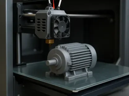
The capacity for seamless data exchange was also expanded, reinforcing the software’s role as a versatile utility for format wrangling and inspection across diverse technical ecosystems. It maintained robust support for a massive array of industry-standard formats, including STEP, IGES, OBJ, STL, DWG, DXF, and IFC. This broad interoperability made it an ideal staging area for 3D printing enthusiasts and professionals who needed to clean up or convert mystery geometry from various sources. The ability to import complex files, perform minor adjustments, and export them in a standardized format was a significant advantage for multi-software pipelines. This versatility ensured that the application could serve as a bridge between different engineering departments, facilitating a more collaborative approach to product development. Rather than acting as an isolated island, the software functioned as an essential node in a larger digital production network. This interoperability was key to its growing adoption in environments where data consistency is a mandatory requirement for success.
Evolution of Manufacturing and Simulation Modules
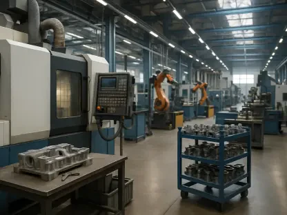
The specialized workbenches received substantial upgrades that moved the platform toward a more integrated and dynamic manufacturing environment. Specifically, the CAM workbench featured a completely overhauled tool library system that improved the organization and retrieval of machining parameters. This update allowed for more sophisticated path planning and better management of tool specifications, which are critical for high-precision CNC operations. By streamlining the link between the 3D model and the manufacturing instructions, the software reduced the risk of errors during the translation phase. Furthermore, the Assembly and FEM modules now included improved templates that facilitated the setup of complex structural analyses. These improvements suggested a move toward a holistic design-to-production workflow where the engineer could manage every stage of the product lifecycle within a single open-source ecosystem. The focus on professional manufacturing needs demonstrated a commitment to supporting the entire engineering process rather than just the initial conceptual modeling phase.
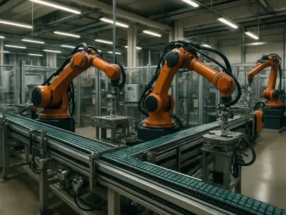
In addition to improved library management, the introduction of animation capabilities within the simulation workbenches provided a more intuitive way to verify mechanical movements. Being able to visualize the motion of an assembly allowed designers to identify potential interference issues before physical prototypes were even considered. This dynamic feedback loop was essential for optimizing the performance of mechanical linkages and ensuring that all moving parts operated within their intended tolerances. The integration of these features meant that simulation was no longer a separate, arduous task but a natural extension of the design process. As the software continued to mature, these capabilities provided the necessary tools for conducting rigorous testing under various load conditions. The enhancement of the FEM environment also allowed for more precise mesh generation and faster solver execution, which were vital for time-sensitive projects. Collectively, these advancements provided a robust framework for handling advanced engineering challenges, making the software more competitive with enterprise-level solutions.
Strategic Implementation and Long-term Growth
The successful deployment of these updates provided a clear pathway for organizations to integrate open-source modeling into their existing infrastructure. It was determined that the most effective strategy involved using the software as a primary tool for format conversion and preliminary geometric cleanup before migrating data to larger simulation environments. This approach allowed teams to leverage the software’s extensive interoperability while minimizing the risks associated with fully replacing established proprietary systems. Engineering leads discovered that by adopting this modular implementation, they could reduce licensing costs starting from 2026 through 2028 without sacrificing productivity or data fidelity. The improved user interface also lowered the barrier to entry, enabling faster onboarding for junior designers who were already familiar with modern software ergonomics. The shift toward direct viewport manipulation and enhanced visual feedback facilitated a more natural learning curve, which was historically a significant hurdle for the community-driven platform.
Moving forward, the focus shifted toward expanding the automation of repetitive tasks through the use of integrated scripting and refined macro capabilities. Professional users were encouraged to develop custom toolsets within the software to handle niche engineering requirements that were not covered by standard features. This flexibility proved to be a major advantage for firms specialized in bespoke manufacturing or rapid prototyping, where unique workflows were the norm. The community demonstrated that by contributing to the shared library of workbenches, the platform could evolve much faster than traditional software cycles allowed. Strategic partnerships between independent developers and industrial users ensured that the most critical needs of the sector were prioritized in subsequent minor releases. This collaborative model fostered a resilient ecosystem that was less susceptible to the market fluctuations of commercial providers. By 2027, the emphasis was placed on further refining the assembly management system to handle even larger datasets with greater stability, ensuring the software remained a staple in professional toolkits.